
There is no code writing necessary to complete this application.
There is no need to know Delphi or C++ Builder in order to create this application.
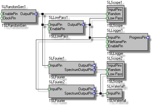
Here is what our application will do:
All of this will be done in less than 2 minutes, and without writing a single line of code.
The steps bellow are captured using Delphi 2007, however they are identical in C++ Builder and older versions of the products.
The tutorial covers the following steps, which should take less than 5 minutes:
1. Add a TSLRandomGen Component to Your Application's Form:
1.1. From the SignalLab tab of the component palette drop a ![]() TSLSignalGen component.
TSLSignalGen component.
2. Add a TSLLowPass Component to Your Application's Form:
2.1. From the SignalLab tab of the component palette drop a ![]() TSLLowPass component.
TSLLowPass component.
3. Add 2 TSLFourier Components to Your Application's Form:
3.1. From the SignalLab tab of the component palette drop 2 ![]() TSLFourier components.
TSLFourier components.
4. Add a TSLLogger Component to Your Application's Form:
4.1. From the SignalLab tab of the component palette drop a ![]() TSLLogger component.
TSLLogger component.
5. Add 2 TSLScope Controls to Your Application's Form:
5.1. From the PlotLab tab of the component palette drop 2 ![]() TSLScope controls.
TSLScope controls.
6. Add a TSLWaterfall Control to Your Application's Form:
4.1. From the SignalLab tab of the component palette drop a ![]() TSLWaterfall control.
TSLWaterfall control.
7. Add 2 channels to both SLScope1 and SLScope2:
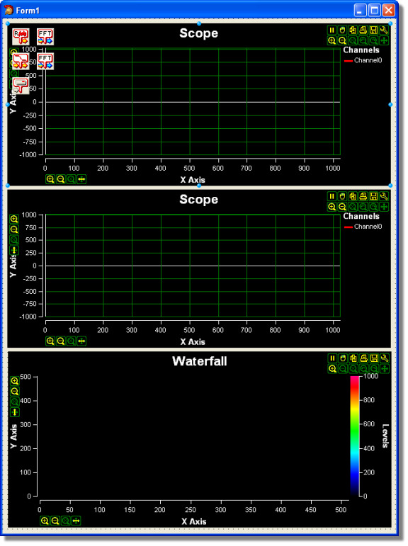
7.1. Double-click on the SLScope1 component on the form:
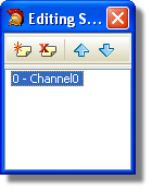
7.2. Select Channel0 in the channel editor:
7.3. In the Property Editor change the name of the channel to “Random”:
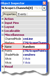
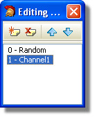
7.4 In the Channel Editor click on the![]() to add a new channel, and select it:
to add a new channel, and select it:
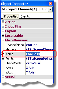
7.5. In the Property Editor change the name of the channel to “LowPass”:
7.6. Repeat the same steps with SLScope2 so it will also have 2 channels named “Random”, and “LowPass”.
8. Connect the SLRandomGen1.OutputPin to SLScope1.InputPins.Random, SLLowPass1.InputPin and SLFourier1.InputPin:
8.1. Select the SLRandomGen1 component on the form:
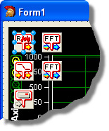
8.2. In the SLRandomGen1 Properties select OutputPin and click on the ![]() button:
button:
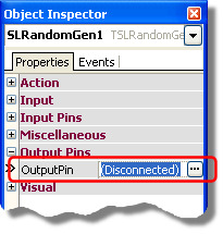
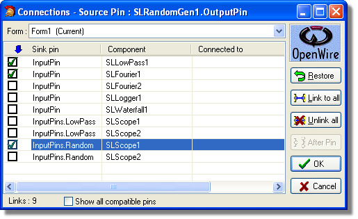
8.3. In the connection editor check the InputPins.Random of the SLScope1, InputPin of SLLowPass1 and InputPin of SLFourier1, then click OK:
9. Connect the SLLowPass1.OutputPin to SLScope1.InputPins.LowPass, SLLogger1.InputPin and SLFourier2.InputPin:
9.1. Select the SLLowPass1 component on the form:
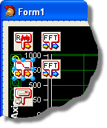
9.2. In the SLLowPass1 Properties select OutputPin and click on the ![]() button:
button:
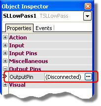
9.3. In the connection editor check the InputPins.LowPass of the SLScope1, InputPin of SLLogger1 and InputPin of SLFourier2, then click OK:
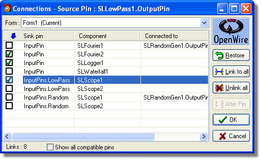
10. Connect the SLFourier1.OutputPin to SLScope2.InputPins.Random:
10.1. Select the SLFourier1 component on the form:
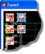
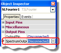
10.2. In the SLFourier1 Properties select SpectrumOutputPin and click on the ![]() button:
button:
10.3. In the connection editor check the InputPins.Random of the SLScope2, and click OK:
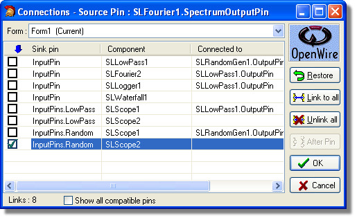
11. Connect the SLFourier2.OutputPin to SLScope2.InputPins.Random and SLWaterfall1.InputPin:
11.1. Select the SLFourier2 component on the form:
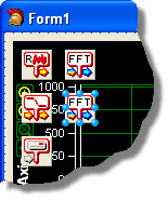
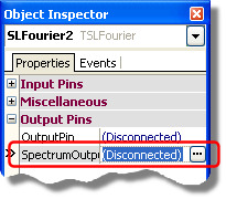
11.2. In the SLFourier2 Properties select SpectrumOutputPin and click on the ![]() button:
button:
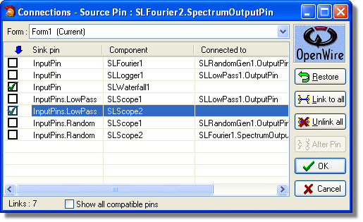
11.3. In the connection editor check the InputPins.LowPass of the SLScope2, and InputPin of the SLWaterfall1, then click OK:
12. Select file name for the file to be recorded by the logger1:
12.1. Select the SLLogger1 component on the form:
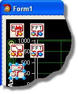
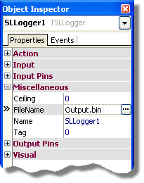
12.2. In the SLLogger1 Properties select the FileName property and enter the path and the name of the file where you want to record the processed data:
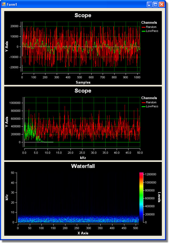
13.1 Press (F9) to run the application. You should see result similar to this one:
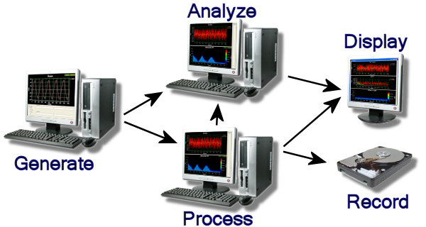
Here is a diagram of the OpenWire connections in this application:
